Since a part of the project we are considering involves Arduino-based payloads communicating with a central Raspberry Pi-based flight computer, my first experiments this week focused on that part. I’ve started experimenting with Serial, and left the two other communication interfaces (I2C and SPI) for later.
Serial has the advantage of being very simple to use both in C and on Arduino. The major downside is that a serial bus is meant to link only two devices, where I might have multiple payload daughterboards connected to the Flight Computer.
Payload Serial Bus (first draft)
- Each payload has four connections to the Flight Computer:
- Tx/Rx serial pins, all connected to the same serial line on the Pi,
- a Communication Request pin (
CRQ) connected to a GPIO pin, - a Communication Authorisation pin (
CAU) connected to a GPIO pin.
-
Whenever a payload has acquired data it needs to transmit, it pulls its
CRQpin high to signal the Pi data is available, and waits. -
The Flight computer runs a basic cyclic executive with the following synopsis:
- List all payloads with a high
CRQpin. - For each waiting payload:
- Pull the
CAUpin high. The payload sends its data. - Read data, possibly send data to the payload.
- Log data to a local file, and add it to the radio queue.
- Pull the
- Send packets in the radio queue to the radio module.
GOTO 1
- List all payloads with a high
Before putting together the first prototypes, a few obvious gotchas come to mind with this architecture:
-
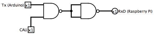
Each payload’s line needs to be protected, in case a bug in the payload’s code causes it to transmit data when it’s not allowed to. That can be solved by
ANDing each payload’sRxandTxlines with itsCAUline. No signal will go through if the Pi hasn’t told the payload to communicate. -
There would need to be some sort of timeout or priority system to avoid one payload transmitting forever and never releasing control of the bus.
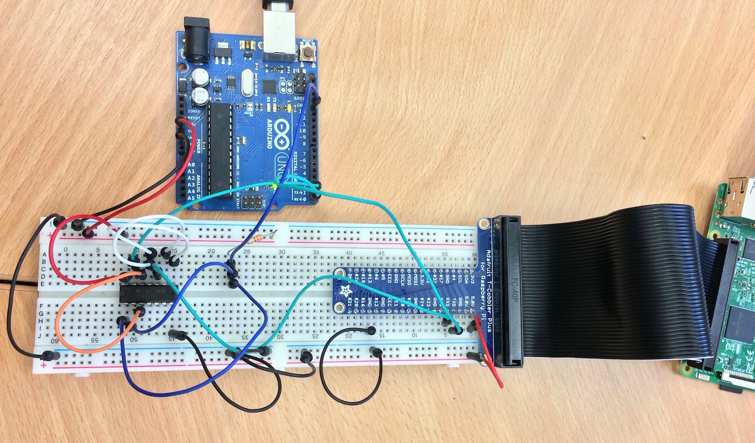
First Prototype
Since I have never used serial with anything but the Arduino library and “nice” GUI serial monitors (the Arduino IDE), I started with something simple:
- an Arduino that transmits “Hello World!” every 100 millisecond when pin 13 is high,
- a raspberry Pi C program that displays whatever is received over the GPIO serial line.
For the moment, the Arduino’s CAU pin 13 is triggered manually, by pulling it high with a resistor to +5v.
Arduino Setup
The Arduino was by far the easiest part of the system to setup. Hardware-wise, the Tx line is connected to the Pi’s RxD GPIO line. I didn’t have any AND gates to protect the serial line, so I built one using a two NAND gates from a spare CD4011be chip I had:
I used the Arduino libraries for this prototype, so the code is more or less as simple as it can get:
:::c
// The pin used as the Com. Authorisation line.
#define PIN_AUTH 13

void setup() {
    Serial.begin(9600);
    pinMode(PIN_AUTH, INPUT);
}

void loop() {
    // Every second, check if the Auth line is high,
    // and if it is, send the message
    if(digitalRead(PIN_AUTH) == HIGH) {
        Serial.write("Hello, world!");
        Serial.write('\n');
    }
    delay(1000);
}
Raspberry Pi Setup
The setup on the Raspberry Pi was a bit more involved, because I have a Pi 3. On that hardware generation, the main serial interface (uart0) is used by the bluetooth chip, leaving only the sub-par miniUART interface for GPIO serial.
After a bit of fiddling, it turns out the best solution for my case is to simply disable the Bluetooth chip and re-map uart0 to the Tx/Rx pins, as explained in this StackOverflow thread. Once this is done, the TTY console must be disabled like on every Pi: otherwise, the boot process outputs debug info on the lines.
Once this is done, any program can access the GPIO Tx/Rx lines by opening the /dev/ttyAMA0 file. The test program loops until some data is available, and displays any received string on the output.
:::c
#include <stdio.h>
#include <unistd.h>
#include <fcntl.h>
#include <termios.h>
#include <stdint.h>
#include <stddef.h>

typedef uint8_t byte_t;

int main(int argc, const char** argv) {
    int stream = -1;

    // Open a file descriptor to the serial port
    stream = open("/dev/ttyAMA0", O_RDWR | O_NOCTTY);
    if(stream < 0) {
        fprintf(stderr, "unable to open serial connection");
    }

    // configure the serial reader
    struct termios options;
    tcgetattr(stream, &options);
    options.c_cflag = B9600 | CS8 | CLOCAL | CREAD;
    options.c_iflag = IGNPAR;
    options.c_oflag = 0;
    options.c_lflag = 0;
    tcflush(stream, TCIFLUSH);
    tcsetattr(stream, TCSANOW, &options);

    // Loop forever and display data whenever it's available
    // on the serial line.
    byte_t rxBuffer[512];
    ssize_t rxLength = 0;

    while(1) {
        rxLength = read(stream, (void*)rxBuffer, 512);
        if(rxLength == -1) { continue; }
        rxBuffer[rxLength] = '\0';
        printf("%s", rxBuffer);
    }

    close(stream);
    return 0;
}
The serial reader is initialised with the Arduino’s standard parameters: 8-bit words, 1 stop bit, no parity bits, at 9600 bauds. Here, read operations are blocking (the read() call doesn’t return until data is available) because it was simpler to write. Future prototypes will use non-blocking calls by calling open() with the O_NDELAY flag. (documentation)
Debriefing
Overall, the system seems to work, at least with a single payload. This week’s goal will be to try and add multiple payloads to check whether the bus can handle scaling.
After a bit of testing, I found one problem. Since I was controlling the CAU line manually by connecting as disconnecting the line, a low state meant the pin wasn’t connected to anything. The problem is, any background electrical noise will be enough to change the state of the pin randomly. Two solutions exist:
- Never disconnect the pin, but instead pull it low by connecting it to the ground through a resistor.
- Invert the logic, by signalling authorisation through a low signal. This way, the input is triggered only when the pin is pulled low. This is what most IC chips use: instead of having a
CS(chip select, or chip enable), they use a/CS(not chip select) pin.
The next step will be adding more Arduinos to that setup, and possibly trying to convert it to SPI (which already implements a Chip Select system as part of the protocol).