My goal this week was to get the most basic radio communications setup working: Arduino or Raspberry Pi at one end, transmitting data (text and images) to a computer acting as the ground station.
Because of frequencies and power limitations in the UK, the module I’ve used so far is the Radiometrix NTX2B. The module operates in the 434.75 MHz band at 10 mW, which is one of the few bands that can be used for airborne transmission in the UK.
PWM vs. Voltage Divider
The first version of the circuit used one of the Arduino PWM pins, to apply two different levels of voltage to the NTX2B (logical 0 and 1).
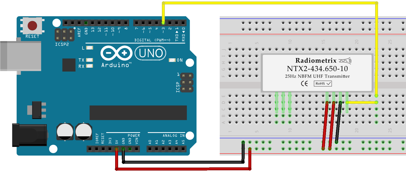
This solution has two main problems:
-
Applying a given voltage is done through PWM, which means the pin oscillates fast between 0V and 5V. This could potentially introduce perturbations in the RF frequency.
-
Raspberry Pis don’t have a real-time clock, and thus can’t generate a precise PWM signal on GPIO pins.
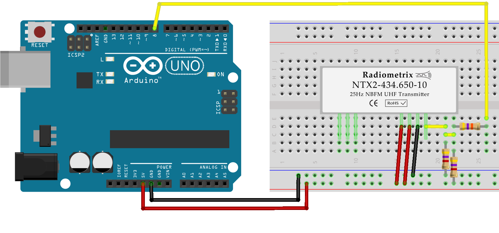
By using a voltage divider on the TXD pin instead, I can use a digital pin. The voltage divider will convert the logic levels (0V and 3.3V/5V) to two voltages determined by the three resistors’ values. With two 4.7kΩ resistors and a 43kΩ to the Arduino pin, logical 0 yields 2.37V, logical 1 yields 2.63V. The 0.26V shift gives a ~520Hz frequency shift.
| Vcc | R1 | R2 | R3 | Voff | Foff |
|---|---|---|---|---|---|
| 3.3v | 4.7kΩ | 4.7kΩ | 20kΩ | 0.34v | 693Hz |
| 5.0V | 4.7kΩ | 4.7kΩ | 43kΩ | 0.26v | 518Hz |
RTTY
The AVR code is fairly basic: for each bit sent to the radio, the radio pin is pulled low or high, and then the programme waits a set amount of time before sending the next bit. Each sequence of eight bits is preceded by a start bit (0) and followed by two stop bits (1). When no data is being transmitted, the line is held high.
:::c
#include <util/delay.h>
#include <avr/io.h>
#include <stdio.h>
#include <stdint.h>
#define RADIO_PIN 5 // PORTB[5] -> pin 13
// Write a single bit to the radio
void rtty_write_bit(char b) {
// Check only the LSB
if(b & 0x01) {
PORTB |= 1 << RADIO_PIN;
} else {
PORTB &= ~(1 << RADIO_PIN);
}
_delay_us(3370); // ~1000000/300 - time for logic
}
void rtty_write(char c) {
rtty_write_bit(0); // Start bit
for(uint8_t i = 0; i < 8; ++i) {
rtty_write_bit(c);
c = c >> 1; // shift the LSB away
}
rtty_write_bit(1); // Stop bit 1
rtty_write_bit(1); // Stop bit 2
}
void main(void) {
// Set TXD as output, pull high
DDRB |= 1 << RADIO_PIN;
PORTB |= 1 << RADIO_PIN;
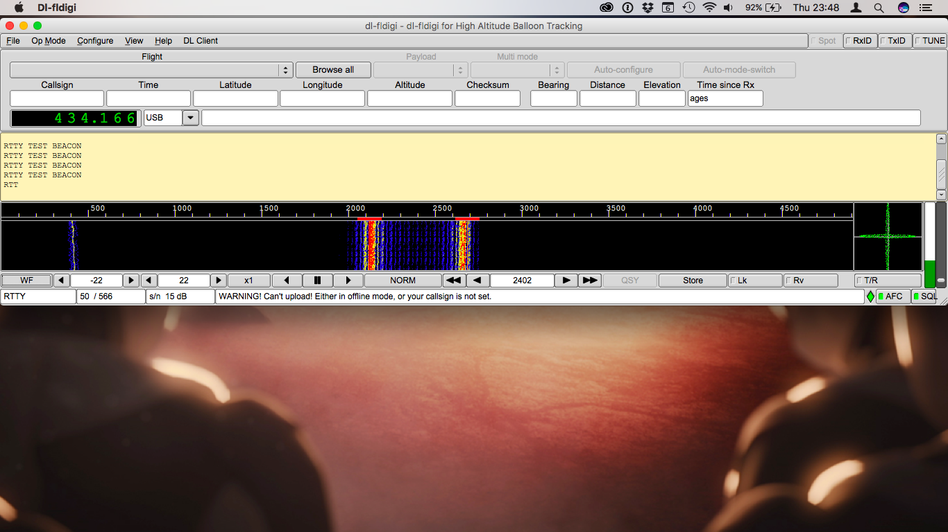
const char* message = "RTTY TEST BEACON\n";
// Main run loop
for(;;) {
// Copy the message pointer and send each character until
// a null byte is found
const char* cptr = message;
while(*cptr != '\0') {
rtty_write(*cptr++);
}
_delay_ms(2000); // 2 seconds between messages.
}
}
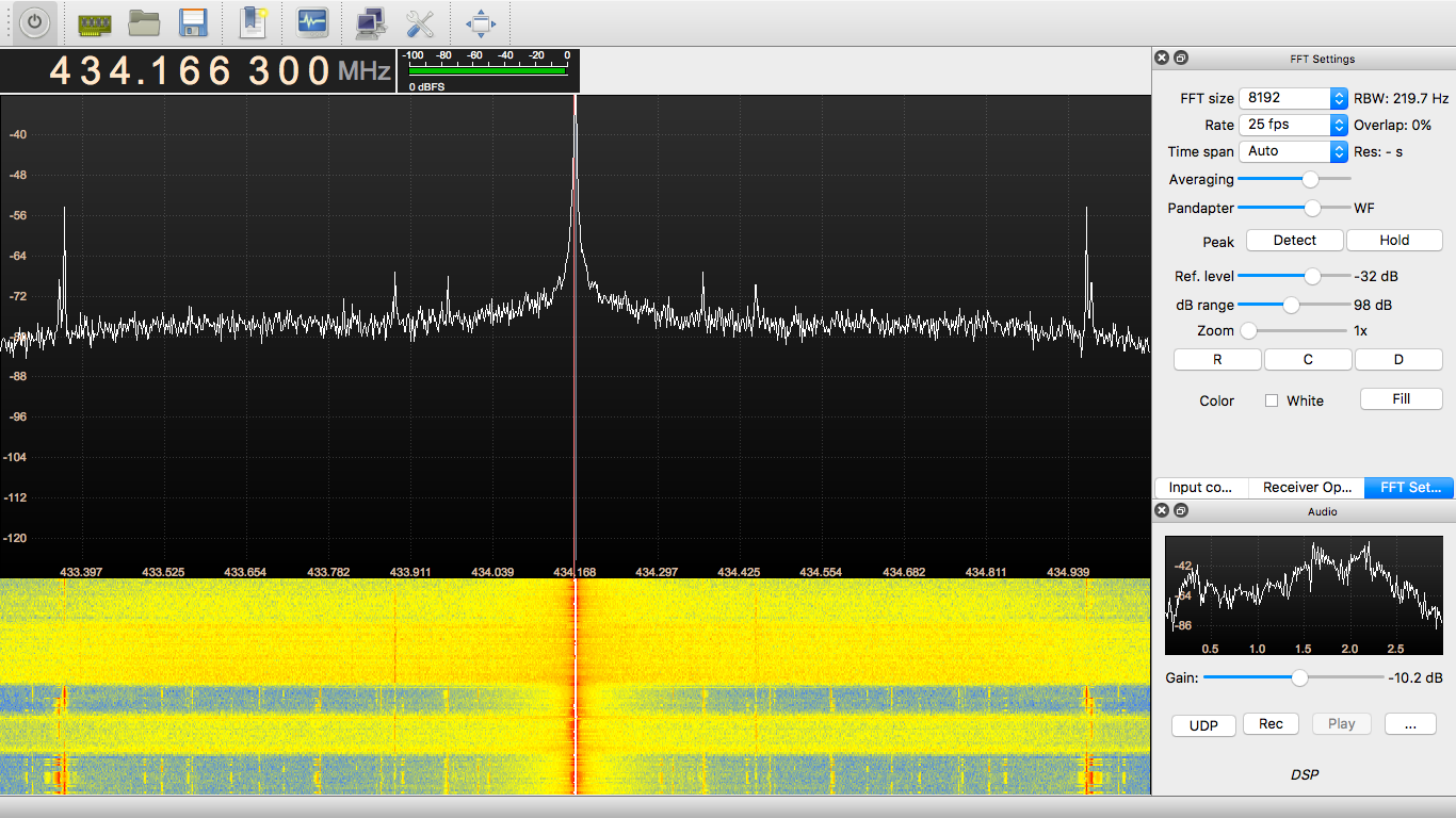
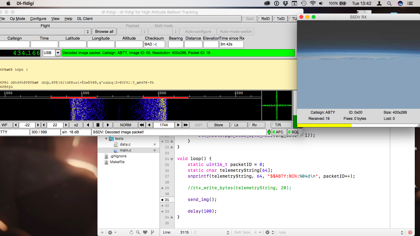
Once the radio module is wired and the Arduino transmitting, the reception uses a £10 Software-Defined Radio receiver, which output is sent to GQRX. Once the tuning is done in GQRX, the audio output is sent to dl-fldigi through Soundflower.
I used the exact same code to send images after encoding them to SSDV. I used the xxd BSD tool to export the binary data as a uint8_t array, which the AVR can then read and transmit, one byte at a time. SSDV works fairly well (it divides images in 256-byte packets with its own error correction code) but can take a few minutes for even small images — at 300bps, there isn’t really anything that can be done.
Raspberry Pi
Because Raspbian (based on Debian Linux) is not a real-time OS, I couldn’t rely on the system’s clock to generate valid 50 or 300bps RTTY signals from the Pi. The solution is to use the Serial/UART chip to do it: RTTY with 8 bit, no parity bits and two stop bits uses exactly the same pulse train as UART 8N2.
The voltage divider is connected to the UART Tx pin on the Pi, and the C code is exactly the same as if I were talking to a serial device.
:::c
#include <stdio.h>
#include <unistd.h>
#include <fcntl.h>
#include <termios.h>
#include <stdint.h>
#include <stddef.h>
#include <string.h>

typedef uint8_t byte_t;
static const char* string = "RTTY TEST BEACON\n";

int main(int argc, const char** argv) {
    int stream = -1;

    // Open a file descriptor to the serial port
    stream = open("/dev/ttyAMA0", O_RDWR | O_NOCTTY/*i | O_NDELAY*/);
    if(stream < 0) {
        fprintf(stderr, "unable to open serial connection");
    }

    // configure the serial reader
    struct termios options;
    tcgetattr(stream, &options);
    // 300bps, 8 bits, 2 stop bits
    options.c_cflag = B300 | CS8 | CSTOPB | CLOCAL | CREAD;
    options.c_iflag = IGNPAR;
    options.c_oflag = 0;
    options.c_lflag = 0;
    tcflush(stream, TCIFLUSH);
    tcsetattr(stream, TCSANOW, &options);

    // Send the string every 5 second
    while(1) {
        write(stream, string, strlen(string));
        sleep(5);
    }

    close(stream);
    return 0;
}
Debriefing
I now have a working RTTY transmitter. On the AVR version, there is one major flaw: since the transmission rate is generated by delays (busy wait loops), the programme blocks until every byte has been sent. Since images can take upwards of five minutes to send, that’s not acceptable. So this week, my goal is to work around that by using timers interrupts.